Math Library
I wanted to be able to display 3D scenes with a camera and possibly animations, so the first component I wrote was a simple vector math library. The code defined vector and matrix structures and common operations for them, as well as a simple matrix stack for animation transforms. The math library was also responsible for transforming raw triangle data into the coordinate system of the viewport.
Triangle Rasterization
The most important piece of code in the project was the triangle rasterizer itself. It took as input a set of transformed triangle data and determined which pixels on the screen needed to be filled and which did not.
I chose to use an algorithm based on barycentric coordinates rather than a more traditional scan line approach. While scanlines are faster and make more sense for a serial rasterizer, they’re less than ideal for hardware that emphasizes parallel execution like GPUs. One of the goals for the project was to gain a better understanding of modern graphics hardware, so scanline based approaches were off the table. I did a lot of research on different techniques and ended up implementing one that was apparently close to the way GPU rasterizers work. This blog series was particularily insightful.
A very basic triangle rasterization output:
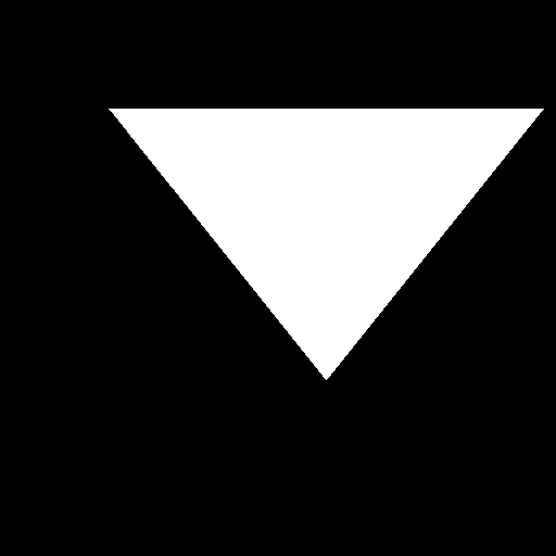
The core rasterizer implementation turned out to be fairly straightforward to write, and most of my time was spent tweaking and fixing the matrix handling code. With the essential bits working correctly, I moved on to more visually pleasing aspects.
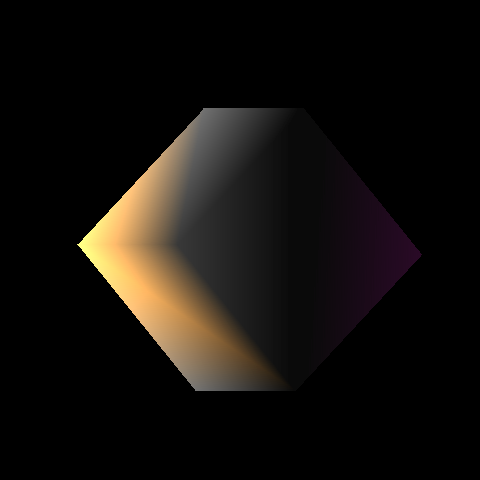
Vertex Attributes
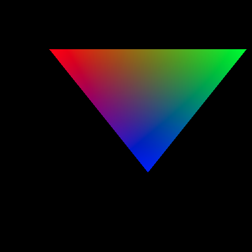
After implementing the basic rasterization algorithm, I worked on adding vertex attribute support. A vertex attribute is essentially a piece of data that is associated with a particular vertex in a triangle. Generally attributes are mathematical types like vectors, scalars, matrices or colors. When a pixel inside of a given triangle is rendered, the attributes of each vertex in the triangle are interpolated over the surface to arrive a single value for that pixel. This is done by computing interpolation coefficients, which are the barycentric coordinates for the pixel relative to the vertices.
The algorithm I chose to use for rasterization produces these coefficients with almost no extra computational cost – this is one of the strong points of the algorithm. To test out the VA handling, I added support for colors and normal vectors to the model format. By assigning three different colors to each vertex of the test triangle and blending them per pixel, the following image was produced:
Depth Sorting
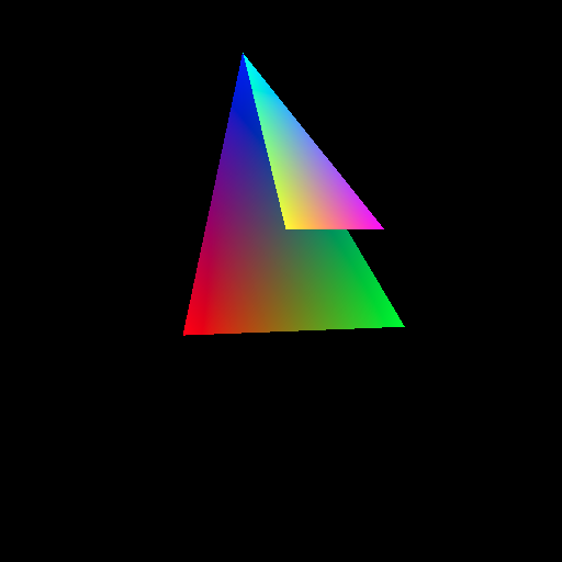
The final piece of code I needed to implement before using the software renderer for 3D content was depth sorting. When two triangles share a region of the screen, a mechanism is needed to determine which ones should be rendered and which is “behind” the other. There are several ways to achieve this, however I ended up using a z-buffer.
For each coordinate on the screen the depth of the last successfully rendered pixel is stored in a secondary array called the z-buffer. Before shading a pixel, the z value of the pixel is calculated by interpolating the vertex positions of the triangle. The draw operation is discarded if the depth is greater the value stored in the z-buffer, since that would imply that a previously drawn pixel should be on top. If the compute value is smaller than the z-buffer value, the pixel is drawn and the z-buffer is updated to the new value.
A simple way to test this was rendering two stacked triangles. In the image below, the small triangle and big triangle share a common vertex, but the big triangle’s lower vertices are “deeper” into the screen than the small triangle:
Putting it all Together
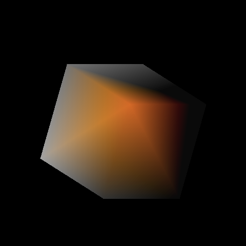
The end goal of the rasterizer was to be able to display 3D surfaces. To do so in a visually pleasing manner, basic lighting features were also needed. This was achieved by using the vertex normals and a single directional light. During rendering the normals were passed from the vertices to the pixel shading logic, where they were dotted with a light vector to determine surface illumination.
The following two images show a spinning cube animation with basic lighting and colors at two of the vertices:
SIMD Acceleration
The rasterization algorithm I used is considered to be embarrassingly parallel. In theory it can scale to any number of execution units since each pixel is processed independently. This makes the algorithm ideal for use with threading or SIMD instructions. SIMD is a means of achieving parallelism on the CPU by performing operations on multiple pieces of data with a single instruction. On Intel, the SSE instructions can be used to perform 4 floating point operations at once, or AVX can be used to perform 8 floating point operations at once.
I ended up extending my rasterizer using AVX to process 8 pixels at a time, rather than processing them all serially. This resulted in a pleasent performance increase. Though I never had the chance to try it, it should also be possible to use multiple threads to improve render performance. The screen could be divided into independent tiles and separate threads could process the triangles in each tile. Some work would be needed to sort triangles into tiles and handle triangles that cross tile boundaries. Matrix math and animation logic could also be offload to another thread.