Optical Dispersion
Dispersion occurs when the index of refraction (IOR) of a material varies as function of frequency; in other words different colors of light refract at different angles. A classic example of this phenomenon is the behavior of white light when directed through a glass prism:

White light passing through a glass prism
When light enters the prism it refracts according to the properties of the material. Lower frequency light (e.g. red) bends at a shallower angle than high frequency light, thus splitting the white light into its colored components. When designing lenses for optical systems such cameras, the effects of dispersion are usually undesirable. The term chromatic aberration is used to describe unwanted discoloration and blurring in an photograph due to the inability to focus all wavelengths of light at the same point. Although most lense systems attempt to reduce or eliminate chromatic aberration, adding a small amount of the effect to renders and video games can help to improve realism. The effect can be used artistically to simulate low end camera footage or distorted vision.
Dispersion in Ray Tracing
Implementing dispersion in a ray tracer is relatively simple. The basic “light as a ray” model used in ray tracing can be modified so that rays also have an wave length associated with them. Rather than working in the RGB color space, ray–surface interactions depend on the wavelength of the ray. This technique is generally refered to as spectral rendering and is supported in most physically-based ray tracing systems. Ignis has a fairly naive implementation that supports either 3 or 6 wavelength values; most serious spectral renderers can be configured to operate with a much wider dataset if desired.
The main drawback of spectral rendering is the performance hit. Since rays must be traced for each potential wavelength, the total number of rays processed for a given scene increases as the number of frequencies involved increases. In Ignis this is addressed by only splitting light rays into spectral components when they interact with a surface that requires spectral rendering, such as a glass prism. For a truly photorealistic scene, however, spectral rendering should be performed on all surface types.
Dispersion in Rasterizers
Implementing a convincing dispersion-like effect in OpenGL is quite different when compared with the ray tracer implementation. Refractive materials require information about the scene behind them, so they are typically rendered in a separate pass with the rest of the rendered scene accessible via a texture. In the refractive rendering pass the view vector and surface normal are used to compute a new refracted light vector. This is then used to compute texture coordinates for sampling the scene texture. GLSL provides a handy refract function that does most of the math for actually computing the refraction vector:
vec3 refractVec = refract(view, normal, iorRatio);
vec4 color = texture(sceneTexture, screenCord + refractVec.xy);
In the above example, view is the normalized view vector, normal is the surface normal at the pixel and iorRatio is the ratio of IORs as described in the GLSL documentation. The sceneTexture variable is a texture sampler to the texture containing the rendered scene, and screenCoord are the base texture coordinates for accessing that texture at the current pixel.
The example can easily be extended to support 3 frequencies of light by treating each R, G and B component seperately. A different IOR ratio is chosen for each of the three colors, resulting in a convincing dispersion effect in the final rendered image. This requires 3 refraction calculations and three texture look ups, which are then summed to produce a final color at the pixel:
vec3 refractVecR = refract(view, normal, iorRatioR);
vec3 refractVecG = refract(view, normal, iorRatioG);
vec3 refractVecB = refract(view, normal, iorRatioB);

vec4 color = vec4(0.0);
color.r = texture(sceneTexture, screenCord + refractVecR.xy).r;
color.g = texture(sceneTexture, screenCord + refractVecG.xy).g;
color.b = texture(sceneTexture, screenCord + refractVecB.xy).b;
color.a = 1.0;
I used the above technique to implement a sort of magnifying glass in WebGL. The lense behaves like a thin disk of glass with a fairly heavy amount of dispersion applied.
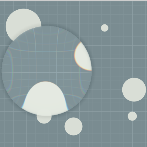
Dispersion in WebGL with 3 frequencies
Improvements
While the basic effect is somewhat convincing, only 3 frequencies of light are used. In some cases this doesn’t provided enough data resolution and banding artifacts can be seen. While working on my ray tracer I stumbled upon a paper that outlines a way to extract 6 different colors values from an RGB space and then compress them back down again after performing computations. This offers marginally more detail and slightly higher dispersion quality at the expense of some extra math and additional texture look ups. In theory the method described in the paper could be extended to an even larger number of different frequencies, however the cost of doing so likely outweighs the benefits.
I implemented a version of the magnifying glass demo based on the method described in the paper. The improvements are somewhat subtle, but the wider color range is apparent:
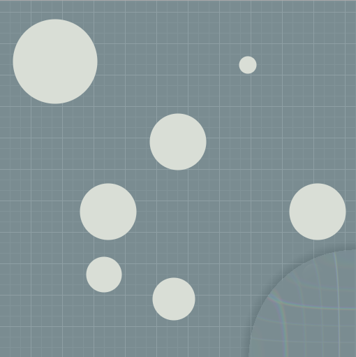
Dispersion in WebGL with 6 frequencies
The high quality version of the lense is available as a WebGL demo.
The same technique also works in 3D. In the WebGL code I construct the surface normals procedurally in the shaders, however in a 3D environment the surface normals of actual objects could be used. The 2D effect might be neat for a sniper scope or telescope lense in-game.