2D Ray Tracing
Last year I experimented with using a 2D ray tracer as a debugging tool when working with new sampling techniques. Running the ray tracer in two dimensions often helped to simplify problems and made it easier to visualize the processes involved. The tool had two modes of operation — the first was a 2D path tracer that emitted rays from a sensor and the second emitted directly from light sources. The latter mode, when I referred to as “light tracing”, was mainly a gimmick. It was occasionally helpful for debugging ray–shape intersection code, though, and produce cool visual results.
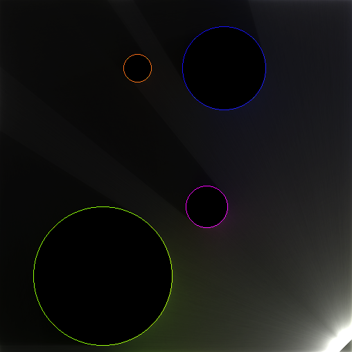
The light tracing mode
The light tracing performance was decent, especially after parallelizing it, so I ended up trying to make it run at interactive framerates. While the resulting demo was fun to play with, the convergence time per frame was still too long for any practical uses.
Enter WebGL
Last weekend I decided to try implementing a similar effect in WebGL. Rather than shading the entire scene with ray tracing code, this time I only used it to find shadowed/occluded regions and darken them accordingly. The rest of the shading was done using standard rasterization techniques. Both the performance and visual quality improved significantly with the WebGL approach. The image below shows the scene I used in my demo; the demo itself can be found in my WebGL portfolio. Moving the mouse changes the location of one of the lights in the scene and clicking anywhere in the canvas will toggle a Gaussian blur effect.
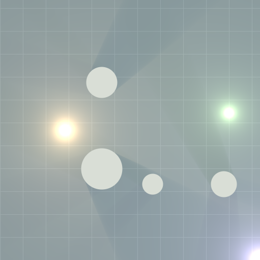
WebGL light tracing, computed per-pixel
Implementation Details
Since it’s written in WebGL, the source code is available on the demo page itself. Admittedly, some portions are a bit convoluted and I haven’t really cleaned it up.
The entire scene is rendered with a single full screen quad. One render pass is made over the quad and a final color value for each pixel is computed based on the scene state. This process produces the lighting and shadows, circular occluders, and the background grid. The Gaussian blur effect is done in two subsequent
The shader starts off with a base color for the active pixel. Modular arithmetic is then used to determine if the pixel is a grid line and the pixel brightness is increased accordingly. Next, each light in the scene is considered. The distance from the pixel to the light is found and an inverse falloff model is used to compute the amount of light that reaches the pixel. Additionally, a darkening factor is computed for the light by comparing it against the occluders in the scene. This is the most interesting portion and the part that is largely based on ray tracing.
To compute the shadows a light ray is traced from each light source to the active pixel. Ray tests are performed on the circles in the scene to determine if the light ray actually reaches the active pixel or if it hits the circle. The result of these collision tests determine if the pixel is shadowed or not. If a pixel is shadowed is darkening factor is assumed to be 0.0, otherwise it’s 1.0.
Since the light sources are treated as points, soft shadowing isn’t present by default. To achieve a smoother edge and fade out of the shadows I introduced a few fudge factors into various portions of the code. These were determined empirically — they have no physical basis whatsoever.
First, the circle–ray collision code was modified to return a value on the range [0.0, 1.0] instead of a simple shadowed/lit boolean. A value of 0.0 still indicated a completely shadowed pixel, but values between 0.0 and 1.0 were used to describe partial/blurry shadowing. When a ray–circle test is performed, one of the intermediate steps is to compute a discriminant when solving the quadratic equation for the intersection. The value of the discriminant tends to be quite small when the ray is approximately tangent to the circle and increases as the ray moves closer to the circle’s center — this property was used to produce the soft shadow approximation. Additionally, the distance from the ray to the light was used to make the the shadow fade out with increased distance. The final formula for the fudge factor was:
where d is the distance from the pixel to the light and D is the discriminant. The scale factor of 0.035 was determined by tweaking the value until a suitable shadow brightness was achieved. The result of the factor expression was added to the original 0.0 or 1.0 value from the ray test and then clamped to the range [0.0 1.0]. Pixels with a small value of D or a large value of d evaluated to large factor values, thus lightening the pixel.
The final step in the rendering process was to shade the gray circles. This was done last so the tops of the circles wouldn’t be shadowed. Circles were filled by simply checking if the active pixel was inside one of the circles and shading that pixel accordingly.
Performance and Practicality
The demo runs quite nicely on all the machines I’ve tested it on, however there are definitely some areas that need optimization. For larger numbers of occluders a quad tree acceleration structure could be used to speed up the ray tracing step. Right now the demo only works with point lights and circular occluders — ray testing against arbitrary shapes should be possible, but requires additional collision routines. That said, the technique isn’t really necessary in most cases. A similar effect can be replicated using a 2D variant of shadow mapping, which also scales better for larger scenes and more complex objects.
One thing I’d like to do is try the faked soft shadowing approach used here in a traditional single-bounce ray tracer. I’m curious how the results compare to a path tracer with true soft shadowing and area light support. In terms of performance the faked shadow version would be significantly faster, at the expense of global illumination quality. If the results are sufficiently convincing, the faked shadows could be used for early test renders before committing to a long render time in a proper path tracer.